Offline
The sample is taken away and analyzed somewhere else, typically in a laboratory, hours or days later.
In SPE: a cartridge by hand, the eluate collected in a vial and injected later.
Sample preparation
Offline, atline, online, inline. What the four words mean, why I call my approach inline, and how a renewable sorbent bed ended up inside the injection loop of an HPLC.
Before going into the chemistry, a word on vocabulary, because this whole post rests on one of these four words. They come from process analytics, where they are defined in the FDA’s Process Analytical Technology guidance (2004) and in ASTM E2363. The dividing line between them is simple: where does the sample go, and is any of it taken out of the stream?
The sample is taken away and analyzed somewhere else, typically in a laboratory, hours or days later.
In SPE: a cartridge by hand, the eluate collected in a vial and injected later.
The sample is removed and analyzed close to where it was taken, with a manual or robotic transfer in between.
In SPE: a robotic station beside the HPLC that mimics the manual procedure and hands over a vial.
Part of the stream is diverted automatically to the analyzer. It may return to the stream or not.
In SPE: the extraction is coupled to the chromatograph, and a fraction of the eluate is cut and parked in a loop before injection (heartcut).
Nothing is withdrawn or diverted. The operation takes place inside the stream itself.
In SPE: the sorbent sits in the injection loop, and the mobile phase carries the retained analytes straight into the column.
In the liquid chromatography literature, most people would call what I do “online SPE”. So why insist on inline?
The criterion: follow the analyte, not the liquid
What classifies a setup is whether the analyte ever leaves the closed fluidic circuit. How much liquid reaches the column is irrelevant.
The perfusate going to waste does not change it. In any solid phase extraction the matrix ends up in the waste, by construction. If that alone disqualified the term, no SPE could ever be called inline. In my setup the sorbent occupies the injection loop, and the mobile phase crosses it and carries the analytes directly to the column: no intermediate collection, no vial, no manual step, and no fraction of the eluate cut away. A heartcut, by contrast, diverts a fraction of the flow, and that is online by definition.
Online stuck in LC for historical reasons, not logical ones. The word appeared in the column-switching literature of the 1980s as the opposite of offline. The question being named was whether the extraction was connected to the chromatograph or done by a person holding a cartridge. With only two cases to tell apart, a third word was never needed. Flow analysis did need three, because there the manifold is the analytical path itself, and that community adopted inline.
LC itself uses inline, and consistently. It reserves the word for whatever is physically installed in the fluid line and acts on the flow: inline filters, inline degassers, inline mixers, inline UV, pH and conductivity sensors in process chromatography. A sorbent bed packed inside the injection loop is literally inside the line.
Two boundaries, two words. Inline describes the coupling inside the instrument. A deployed PalmChrom, taking water from a river and not returning it, is an online analyzer with respect to that river. The two statements do not contradict each other, because they describe different boundaries.
An honest caveat
The distinction is not settled in the literature. The closest precedent, SPE coupled to capillary electrophoresis with the micro-cartridge inside the capillary, has been published under both names. No authority decides it, so the only safe move is to define the term once and stick to it. In this blog, inline means that the sorbent occupies the injection loop and the eluate reaches the column without leaving the fluidic circuit.
High performance liquid chromatography (HPLC) is possibly the most widespread instrumental technique of the modern analytical laboratory. It is the technique behind the release of a batch of medicines, behind the enforcement of residue limits in food, behind the monitoring of contaminants in rivers and drinking water, behind the therapeutic drug monitoring in hospitals and behind the doping controls in sport. In all those cases the number that is finally reported, and upon which a decision is taken, derives from the area of a chromatographic peak. The technique is mature, remarkably reproducible and highly automated, since an autosampler, a high-pressure pump, a column and a detector can be operated unattended for days.
Regretfully, a chromatograph can only separate what is delivered to it. Real samples are rarely injectable as such: the analytes are too diluted to be detected, the matrix contains substances that coelute with them or damage the column, or the medium in which the analytes are dissolved is not compatible with the working principle of the instrument, as it happens with salty media in ion sources. The operations that bring a sample from the vial to a condition suitable for injection are collectively designated as sample preparation, and they constitute the least automated and most critical part of the analytical process.
The relevance of this step is twofold. In terms of time, sample preparation is in most workflows the longest stage of the analytical procedure, well above the chromatographic separation itself, and it therefore governs the sample throughput attainable in a laboratory. In terms of quality, it is the stage in which the largest part of the overall uncertainty originates. This follows directly from its nature: every pipetting, weighing, transfer, evaporation and reconstitution is a manual operation performed in an open vessel, in contact with the laboratory atmosphere, with plasticware and with the residues of the preceding sample, and each of them contributes with analyte losses, with contamination and with a random deviation that propagates to the final result. Contrariwise, the chromatographic separation proceeds in a closed, thermostated and computer-controlled system.
In other words, the easy part of the analysis has been automated, while the difficult part is still executed by hand.
Among the available sample preparation techniques, solid phase extraction (SPE) is by far the most used one, since it addresses simultaneously the preconcentration of the analytes, the removal of the interferences and the exchange of the matrix. In this technique a solid resin is packed in a small reservoir provided with two fluidic connections, the ‘cartridge’. The cartridge is conditioned, the sample is perfused through it, and the analytes bind to the resin while the matrix is washed to the waste. The retained analytes are subsequently mobilized with a small volume of an eluotropic medium, so that they are recovered clean and concentrated by a factor designated as ‘enhancement factor’. When SPE is performed manually, or by a robotic station that merely mimics the manual procedure, it inherits all the drawbacks described above, and in addition only a fraction of the collected eluate is finally injected, that is, most of the analyte that was carefully preconcentrated is discarded.
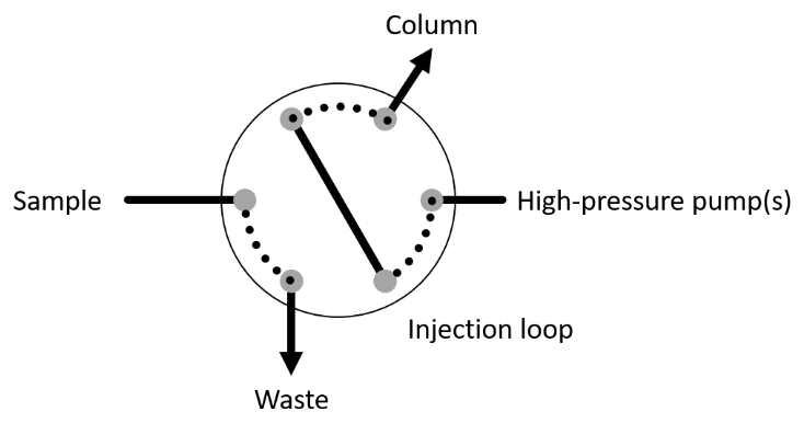
Normally a valve of the type ‘injector’ is used to isolate a given length of tubing, called ‘injection loop’. This length of tube can be independently inserted in two different flow streams, depending on which of the two positions the valve is in (Figure 1). One of the flows normally carries the mobile phase from the high-pressure pump to the chromatographic column, and from there to the detector. In case of gradient elution, more than one pump can be connected to the same input. The other flow is often used to load the injection loop. When the valve is in load position, that is, the injection loop connected between the sample and the waste, the sample is introduced with a syringe, with a pump or with a similar device. The overflow from the injection loop is directed to a waste. Upon valve operation, the injection loop will be connected between the high-pressure pump and the column (inject position). This operation assures that a constant volume is reproducibly injected into the chromatographic column and thus, quantitative data can be obtained from the analysis. The injector can also be operated without a chromatographic column, as in the so-called flow injection analysis systems (e.g., direct infusion in mass spectrometry, chemical derivatization with ICP detectors).
SPE can be applied by hand using commercial cartridges, by robotic stations, which mimic the analyst performance, or in a fully automatic way, in a use that is called ‘inline cartridge’ or ‘online cartridge’ depending on the literature. To that purpose, the resin is packed into a metal case able to withstand the chromatographic pressure and inserted in the injection loop of the injector (Figure 2). The sample is loaded usually from an autosampler. Bracketing the sample with conditioning and washing medium achieves those operations in a single step. If the chemistry of the inline cartridge and the analytical column are the same, there is no need for an elution step, since upon valve switching, the mobile phase will transport the analytes to the chromatographic column on its own. This setup is also known as ‘switching valve’.

There is a need for SPE to be exchanged automatically. This function can be provided by so-called ‘cartridge exchangers’, commercial devices that have a magazine of different cartridges and can select the desired one under software control. They are expensive, and there is a limited selection of commercially available cartridges for them, in terms of different chemistries, particle sizes and bed masses.
Another alternative was proposed by Ruzicka in 1993, and consisted in the fluidization of the micrometric sized sorbent in an adequate medium and the manipulation of the resulting slurry in the fluidic manifold, as if it were another liquid. It is called ‘bead injection’. Small particle spherical sorbents, high viscosity solvents that compensate the sorbent interactions and optimized flow rates ease this manipulation.
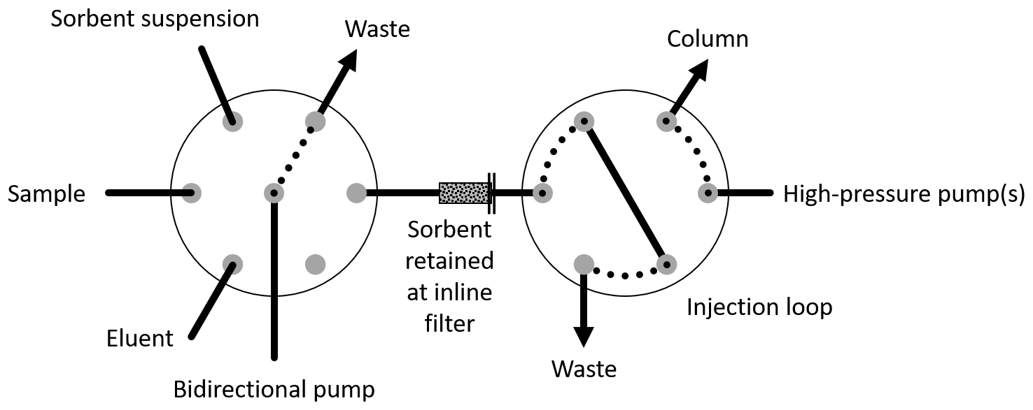
A typical bead injection setup consists of a selector valve, that is, a valve that can connect its central port to any other, and a computer controlled bidirectional pump. The working principle is to connect the pump to the sorbent suspension reservoir and aspirate a defined volume of slurry. The piece of tube between the selector and the bidirectional pump is long enough to prevent the sorbent or other liquids from entering the pump. Afterwards the valve moves to another port, where a tube with an inline frit (a small thick filter) is located. The liquid goes through the frit, but the particles are retained, packing an SPE ‘column’ in situ. This column is treated as any SPE cartridge: it is washed with the carrier, the sample is aspirated from its port and dispensed to the column, the analytes are retained, and the matrix is washed to the waste. Finally, the eluent is accessed from the valve, and a given volume is aspirated and perfused through the sorbent.
A setup where this operation is performed prior to liquid chromatography can be seen in Figure 3. In this case, the eluent volume is critical for the success of the method. The chromatographic injector is in load position, and an exact and optimized volume of eluent perfuses the column, leaving the eluate parked in the injection loop, an operation called heartcut. The injector then switches, injecting the content of the injection loop into the chromatographic stream.
To unpack or dispose of the sorbent, the tube with the frit is selected, and the sorbent is simply reaspirated into the valve and from there disposed to the waste port. The reaspiration is the most complicated step of the bead injection method, and several improvements have been developed to ease it, which include reaspiration at high flow rates (high shear stress), pulsed reaspiration, or wetting the sorbent with additional liquids of high viscosity.
Those skilled in the art tried to take the advantages of the inline cartridges and of the bead injection methodology by inserting the inline frit inside the injection loop, so that the sorbent is trapped inside the injector. The resulting system, herein referred to as ‘heartcutless bead injection’, or popularly ‘bead injection with the beads in the injection loop’, is depicted in Figure 4. It combines the flexibility of bead injection, that is, automatic renewal at will of the sorbent phase and the possibility of selecting the chemistry, bed mass and particle size of the sorbent. Additionally, the elution step is substituted by the mobile phase elution, which is quantitative, does not require sorbent-column orthogonality, and achieves high enhancement factors because the elution volume is reduced to the peak volume.

This setup was often discussed, but for a long time no scientific literature tackled it. While the reaspiration step is already complicated in the classical heartcut bead injection, after compaction by the high-pressure flow, and due to the increased number of interfaces through which the sorbent must travel, the unpacking was never successful.
A possibility for unpacking consists in adding another valve to the setup, herein referred to as ‘reverser’, designed to reverse the flow around the injector (Figure 5). In this setup the selector manipulates the sorbent, which is transferred through the reverser to the injector, where it is retained by the inline frit in the injection loop. Then the sample is loaded and washed, and the analytes are transferred quantitatively to the column upon valve switching. To remove the sorbent, the injector is returned to the load position, the injector is actuated, and the bidirectional pump removes the sorbent with positive pressure, with or without the support of an additional high viscosity liquid.

The sorbent removal with positive pressure is successful because more pressure, and thus more shear stress, can be applied to the sorbent particles in the tube. In the reaspiration scheme, the maximum pressure drop is limited by the vapor pressure of the solvent or carrier in the system: when the pump lowers the pressure below the vapor pressure, the liquid cavitates instead of being displaced. The maximum pressure drop is therefore temperature dependent, and equal to the ambient pressure minus the vapor pressure. Contrariwise, in the removal by positive pressure the cavitation problem does not apply, and even common autosampler pumps reaching ca. 10 bar apply a shear stress more than 10 times higher than in the reaspiration method.
| Liquid | Maximum pressure drop |
|---|---|
| Water | 0.976 bar |
| Isopropanol | 0.942 bar |
| Acetonitrile | 0.878 bar |
| Methanol | 0.813 bar |
A further refinement of the above-mentioned system is envisioned. The high-pressure pump(s) responsible for the chromatography can be substituted by a bypass between the selector and the injector (Figure 6). This is possible because (i) sample preparation and chromatography are time independent, so it is feasible that while one pump is in service the other(s) are not, (ii) several single or multiple piston pumps are commercially available that are both bidirectional and able to exert chromatographic pressure, (iii) low pressure chromatography is a valid separation technique, allowed by monolithic or short core-shell columns, (iv) narrow bore columns allow the whole chromatography to be developed with minute amounts of mobile phase, compatible with the above-mentioned pumps, and (v) the total footprint of the setup is reduced by using fewer fluidic components, which is useful in resource constrained environments such as portable applications.

| Approach | Renewable sorbent | Whole extract injected | Free choice of sorbent | Hardware |
|---|---|---|---|---|
| Manual or robotic SPE | Yes, new cartridge | No, a fraction | No, commercial cartridges | Hands or a robot |
| Inline cartridge | No | Yes | No, tied to the column | Injector and cartridge |
| Cartridge exchanger | Yes | Yes | No, limited catalog | Expensive dedicated unit |
| Bead injection with heartcut | Yes | No, a cut | Yes, bulk sorbent | Selector and injector |
| Selector, reverser and injector | Yes | Yes | Yes, bulk sorbent | Three valves |
| C5-23512D-CU valve | Yes | Yes | Yes, bulk sorbent | One valve and one pump |
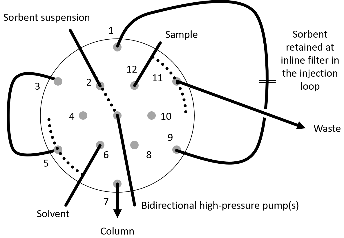
Heartcutless bead injection was first published in my 2024 paper in Analytica Chimica Acta, with the C5-2359-CU valve. Its successor, the C5-23512D-CU, is a single valve with a novel stator and rotor configuration, which combines in one body the functionality of a selector, a reverser and an injector (Figure 7).
With no further external hardware than a bidirectional high-pressure pump, an arbitrary bulk sorbent is packed at will in the injection loop, the sample is loaded and washed through it, the analytes are injected quantitatively into the chromatographic flow generated by the valve itself, and the used sorbent is unpacked with positive pressure. Sample preparation and separation are thereby no longer two separate worlds, with a footprint and a component count compatible with resource constrained environments such as portable applications.
Reserve your device or request early access.