Hardware
C5-23512D-CU: sample preparation and chromatography in one valve
Twelve positions, one bidirectional pump, and all the sample preparation in four valve movements. How the patented valve at the heart of PalmChrom works, position by position.
At a glance
The C5-23512D-CU, is a valve with a novel stator/rotor configuration that allows centralizing the most important operations of sample preparation and liquid chromatography in chemical analysis. The previous post explains the setups it replaces.
- 12positions in one valve body
- 4valve movements for the whole sample preparation
- 1bidirectional high-pressure pump, no separate HPLC pump
| Positions | 12, plus central port |
|---|---|
| Rating | 100 bar at 50 °C, liquids |
| Stator | PEEK, 1/16" fittings, 10-32 UNF |
| Rotor | Valcon E |
| Bore | 0.5 mm |
From the C5-2359-CU to the C5-23512D-CU
The first heartcutless bead injection, published in Analytica Chimica Acta in 2024, was built around the C5-2359-CU, a valve intended to replace the injector of a standard HPLC autosampler. The chromatographic flow still came from the HPLC pump. The C5-23512D-CU integrates that flow in the valve, so the same bidirectional pump prepares the sample and runs the chromatography.
| C5-2359-CU | C5-23512D-CU | |
|---|---|---|
| Role | Injector for a standard HPLC autosampler | Selector, reverser and injector in one body |
| Ports | 6 low-pressure selector ports and 5 high-pressure ports | 12 positions around a central port |
| Chromatographic flow | External HPLC pump | The same bidirectional pump, through a bypass |
| Rating | 100 bar | 100 bar |
| Status | Published in Analytica Chimica Acta, 2024 | Patented |
Ports and positions
The valve combines the functionality of selector, reverser and injector, so it only requires an external bidirectional high-pressure pump to perform sample preparation and chromatography, with a minimal additional footprint and high portability. Two bypasses must be installed: one corresponding to the injection loop, which includes an inline frit for retaining the sorbent in its lumen, and a second one between the selector and the injector functionalities (Figure 1).
The even positions act as a selector: the central port connects to one port, and all other ports are blocked. In the odd positions, two rotor grooves also connect pairs of outer ports, which gives the valve its reverser and injector functionality.
| Position | Central port to | Rotor grooves | Used for |
|---|---|---|---|
| 1 | Port 1, injection loop | 3–5, 9–11 | Packing the sorbent and loading the sample through it, to waste |
| 2 | Sorbent suspension | none | Aspirating sorbent |
| 3 | Port 3, bypass | 5–7, 1–11 | Pressurizing the column through the bypass (optional) |
| 4 | Free | none | Spare: another sorbent, sample or solvent |
| 5 | Port 5, bypass | 1–3, 7–9 | Injecting and running the chromatography |
| 6 | Solvent | none | Aspirating mobile phase |
| 7 | Column | 3–5, 9–11 | Pressurizing the column directly (optional) |
| 8 | Free | none | Spare |
| 9 | Port 9, injection loop | 5–7, 1–11 | Unpacking the used sorbent to waste |
| 10 | Free | none | Spare |
| 11 | Waste | 1–3, 7–9 | Priming lines |
| 12 | Sample | none | Aspirating sample |
One analytical cycle, step by step
-
Aspirate sorbent 2
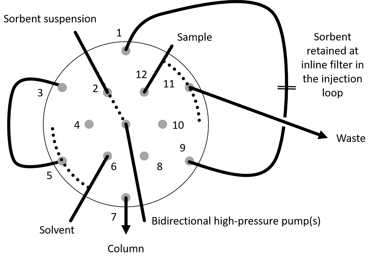
The analytical method starts with the valve in position 2. In this position the bidirectional pump is connected with the sorbent suspension reservoir through a tube long enough to prevent the sorbent from entering the pump.
-
Pack the bed 1
Afterwards, the valve moves to position 1 and dispenses the sorbent. The sorbent flows through the central groove to position 1 and travels through the injection loop. The sorbent is retained by the inline frit, and the liquid continues to the exit of the injection loop and from there, through one of the ancillary grooves, to the waste. Dispensing an additional volume of liquid cleans the sorbent, preparing it for accepting the sample. In Figure 2 it can be seen that the sorbent is packed against the inline frit.
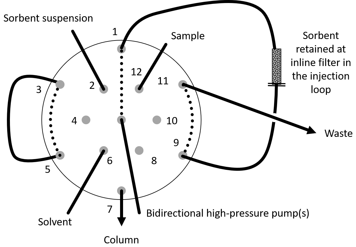
Figure 2. Position 1: the sorbent packed against the inline frit. -
Aspirate the sample 12
Afterwards, the valve moves to position 12 for aspirating the sample.
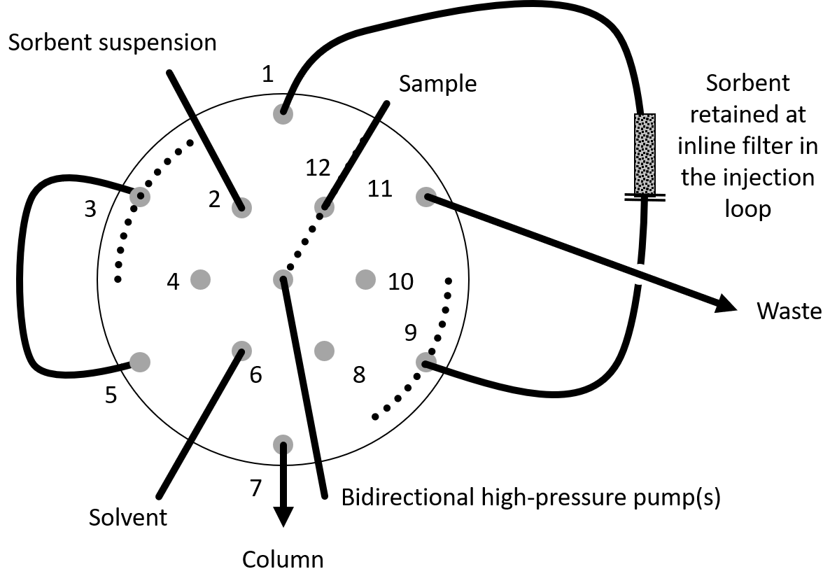
Figure 3. Position 12: aspirating the sample. -
Load the sample 1
After aspirating the sample, the valve moves again to position 1 and dispenses the sample to the injection loop furnished with the sorbent. The analytes stick to the sorbent while the matrix is washed away to the waste through the injection loop and an ancillary rotor groove. At this point, and in only 4 valve movements, all the sample preparation is performed and the system is ready for the chromatography.
-
Aspirate mobile phase 6
For the chromatography, the valve moves to position 6, and the pump aspirates the mobile phase (solvent).
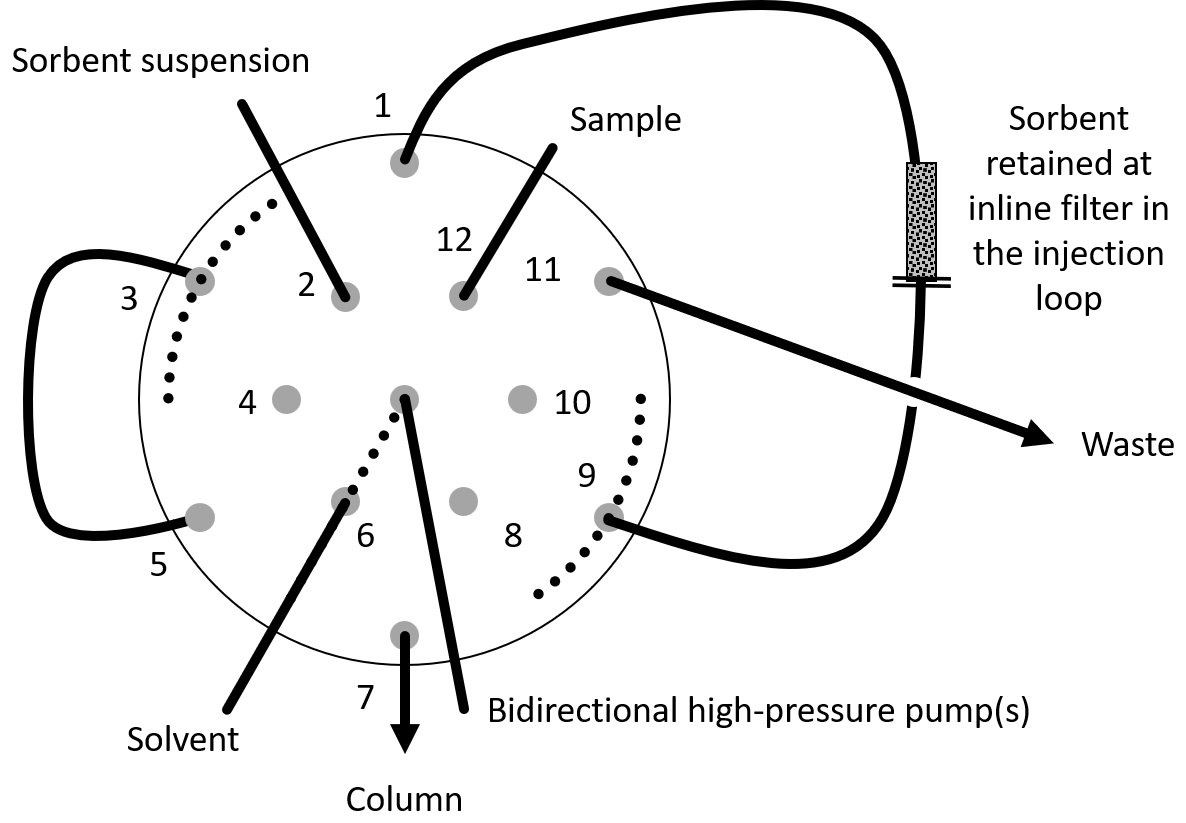
Figure 4. Position 6: aspirating the mobile phase. -
Pressurize the column 7 or 3
Depending on the needs of the system, the column can be pressurized at this point. To do so, the valve is connected to position 7, where the central finger connects the pump with the column. Alternatively, it can be connected to position 3, in which the mobile phase flows through the external bypass and the last groove of the rotor.
-
Inject and separate 5
The next step is to start the chromatography. If the column was not pressurized, the valve simply moves to position 5 and the pump(s) start dispensing the mobile phase. If the column was pressurized, it is best to ‘inject’ with a fast movement toward position 5 (from 3 or 7), with the intermediate port (4 or 6) blinded, so as not to depressurize the system or contaminate this intermediate port.
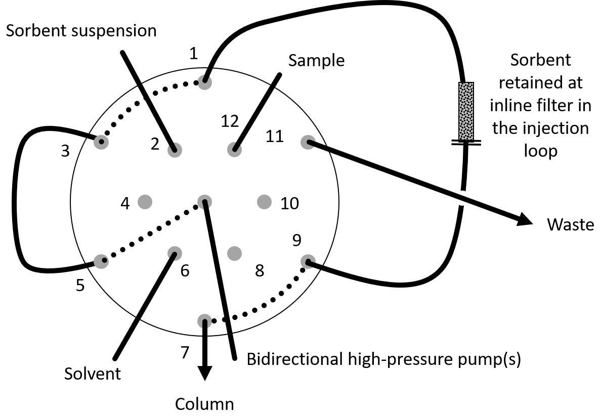
Figure 5. Position 5: the mobile phase crosses the sorbent bed and carries the analytes into the column. -
Next injection 12 1 6 5
When the chromatography is performed, the system is ready for the next injection. For that, the valve goes again to position 12, aspirates the sample, goes to position 1, dispenses the sample to the sorbent, aspirates mobile phase from position 6 and dispenses it again to position 5. In this example the sample is simply aspirated from position 12; in the real case, an autosampler or the analyst will have exchanged the sample. Priming the tubes is also an important factor, especially for the sample: a small aliquot of the sample is aspirated and dispensed to position 11, waste, before the real sample is aspirated and dispensed to position 1.
-
Renew the sorbent 9
If the sorbent is not needed for the next injection, or it is degraded and needs to be removed, or the next sample requires a different sorbent, the steps for sorbent renewal are executed: the valve goes to position 9 and the pump dispenses the carrier (Figure 6). The sorbent is flushed to position 1 and, through the ancillary groove, to the waste in position 11. Then the next sorbent (the same chemistry as before, another one, or several sorbents from those available in the valve) can be loaded. If the sorbent simply needs to be renewed, the valve goes to positions 2 and 1, and is ready for the next sample.

Figure 6. Position 9: the used sorbent is flushed out with positive pressure.
Room to grow
Note that ports 4, 8 and 10 were not used. They are available to accommodate other sorbents, samples, solvents or mobile phases, or can just be left open to air.
What the design brings
Chemically, the valve can
- Pack an amount of sorbent into the external injection loop at will, selected among those available at the selector. This bypasses the sorbent compaction and the irreversible sorption of matrix components, and enables the use of bulk sorbent at mg levels.
- Load the sample through the sorbent-loaded injection loop, trapping the analytes and washing the matrix in a single step.
- Insert the sorbent-loaded injection loop into the stream of the self-generated chromatographic flow.
- Elute the sorbent with the chromatographic mobile phases, that is, without heartcut, thus achieving very high enhancement factors.
- Unpack the sorbent with positive pressure.
Mechanically
- When a selector position is selected, that is, the even numbers, the grooves of the injector functionality block the injector ports, so no undesired flow may occur.
- The interleaving of both port sets allows fabricating the valve with small features and thus high pressure tolerance.
- One valve and one pump replace three valves and two pumps, a component count that fits a 1.7 kg field instrument.
PalmChrom is completing final certification, expected by the end of 2026.
Reserve your device or request early access.